
Architectural Informatics 2 |
AutoCAD 3D·2 • Hobbit House |
Digital Representation |
• Contents: |
Exercise: create the solid model of the hobbit-house shown below!  |
You create complex solid models from basic solid shapes. These "base elements" can be created by extruding a 2D object along a path or revolving it about an axis. There are also base elements that can be created with a single command, like box, cone, cylinder, sphere, torus, and wedge. Once you have created a solid, you can create more complex shapes by combining them. You can join solids, subtract solids from each other, or find the common volume (overlapping portion) of solids. Solids can also be modified by filleting or chamfering their edges.
» In the following example, the origin is supposed to be at middle of the bottom face, and the coordinates are given in meter.
» If they're not already visible, it's suggested to turn on the Solids and Solids Editing toolbars!
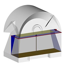
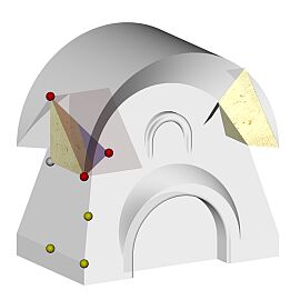
•> Draw the brown rectangle (RecTang -2.5,-1.5,0.5 @5,1.5)!
•> Create the blue box by extruding the PLine (EXTrude, or Draw • Solids > Extrude) . The height of the extrusion should be 2 m.
•> Draw the red PLine by clicking on the ENDpoints of the Box!
•> Rotate the coordinate system (UCS X 90), and draw the blue triangle in its vertical plane!
» The easiest way perhaps is to start with the 0.5 m long horizontal edge.
•> Extrude the blue triangle along the red path (the same Extrude command, but this time with the Path option).
•> Subtract the second solid from the first one! Be careful, since you will have to press [Enter] twice: firstly after selecting the solid(s) you want to subtract from, secondly after selecting the shape(s) you want to subtract.
» Keep the vertical UCS, since this way you don't have to deal with z coordinates!
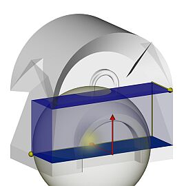
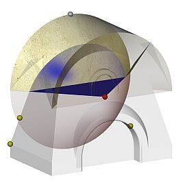
•> Draw another Box (BOX, orDraw • Solids > Box) by it's diagonally opposite corners (-2.5,.5 @5,2.5,1.5)!
•> Draw a Sphere (SPHere, or Draw • Solids > Sphere), by showing it's center (on the MIDpoint of the hind edge of the Box), and by specifying it's radius. The radius can be given by a point on the surface – this point is 1.5 meters away from the center both in x and y directions (@1.5,1.5)
•> The shape we need is the overlapping portion of the two latter solids (INTersect, or Modify • Solids Editing > Intersect).
•> Restore the World Coordinate System, but first save the current one for later use (UCS Save Front W )!
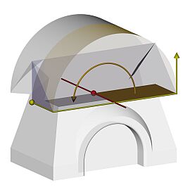
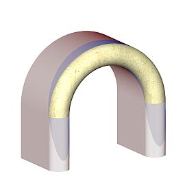
The outer shape of the roof can be created by uniting a semi-cylinder and a wedge.
•> Create the semi-cylinder by revolving the brown PLine around the red axis (another way of course would be to Extrude it).
•> The other (gabled) part of the roof can be created from a Wedge (WEDge, or Draw • Solids > Wedge). Since the height of the Wedge always decreases along the X axis, the UCS should be rotated first (UCS Z -90)! The Wedge can be drawn the same way as the Box: for example by clicking on the point marked with yellow bullet, specifying the opposite (@1.5,5) corner, finally typing (or showing) the height (1.5).
•> The last step is to unite (UNIon, or Modify • Solids Editing > Union) the two parts with the previously drawn elements.
Of course, the shapes underneath the eaves should be Subtracted from the model!
Since there is no pyramidal element in AutoCAD, you'll have to cut off the unnecessary part of a Wedge (or Box) in order to create it. This can be done (for example) with the Slice command.
•> First, create another, shorter Wedge (or Box, if you prefer) with the same base point (marked white), but with it's opposite corner at @1.5,1.5,1.5.
•> Cut off the unnecessary parts of this last shape (SLice, or Draw • Solids > Slice). In the process, you'll have to specify a "cutting" plane (with three of its points), and then the part of the object you want to keep (the other part will be deleted). The first cutting plane should be the one marked with red bullets, the second one is the plane of the wall (yellow bullets). In both cases you'll be prompted to specify which side should be kept – you can show it (for example) by clicking on the ENDpoint marked with the white bullet.
•> Mirror the truncated pyramid to the other side, Subtract both of them from the main shape, then Mirror the result again to get the opposite side, and Union the original and the latter shapes!
•> You can use the Cone (CONe, or Draw • Solids > Cone) element to create the remaining part of the eaves. Since the base circle of the Cone always lies on the XY plane of the UCS, first you should return to the previously saved frontal UCS (UCS R Front). The center point of the base-circle is at the center of the semi-cylinder (0,2.5,-1.5), the radius and the height is 2.5 m (45°).
•> Slice off the unnecessary parts: the bottom half, and the top part, which would be inside the wall's plane. In the first case, you can specify that the cutting plane is parallel with the ZX plane of the UCS, after that you only have to show one point on this plane: for example the apex.
•> Return to the WCS, Mirror the truncated cone to the other side, and Subtract both the original and the latter from the main shape.

•> The entrance can be cut off by Subtracting a Cylinder (CYLinder, or Draw • Solids > Cylinder). The center point (marked yellow) is at the MIDpoint of the bottom plane, the radius is 1.2 m, the height is -0.5 m (-Z direction).
•> The Fillet command can also be used in 3D, this time for rounding off the edge (marked with red) around the entrance (to avoid accidents when non-hobbit visitors arrive).
•> To create the socle, you should Extrude the bottom face of the body (Modify • Solids Editing > Extrude faces). The height of extrusion is 0.5 m, since a positive value means that the face(s) should move outwards from the solid.
•> Finally draw the window by creating a torus (TORus, or Draw • Solids > Torus), cutting of it's unnecessary parts, and extruding it's faces as shown on the picture!
Create the "plans" of the front and side elevations (of course with dimensions) in paperspace!
Strommer L. • BME Department of Architectural Representation